Components calibration
Step-by-step calibration of a power measuring system
Components of a power measuring system for high-voltage applications
A power measuring system in the field of high-voltage technology normally consists of voltage sensors, current sensors and a power measuring instrument. Voltage transformers are most commonly used as voltage sensors. More rarely, voltage dividers are also used. Only current transformers are used for the current sensors. The instrument transformers and the power measuring instrument each have autonomous calibration methods.
Calibration of the instrument transformers
Calibration of the instrument transformers
The calibrations of current transformers and voltage transformers are performed by means of a transformer measuring bridge. Here, the following measurement uncertainties are certified for each measuring range of the instrument transformer:
- Measurement uncertainty of the amplitude of the measuring range
- Measurement uncertainty of the angle of the measuring range
The calibration of the transformers with evaluation of the calibration in the form of amplitude errors and angle errors is shown schematically in the diagram.
Calibration of the power measuring instrument
Calibration of the power measuring instrument
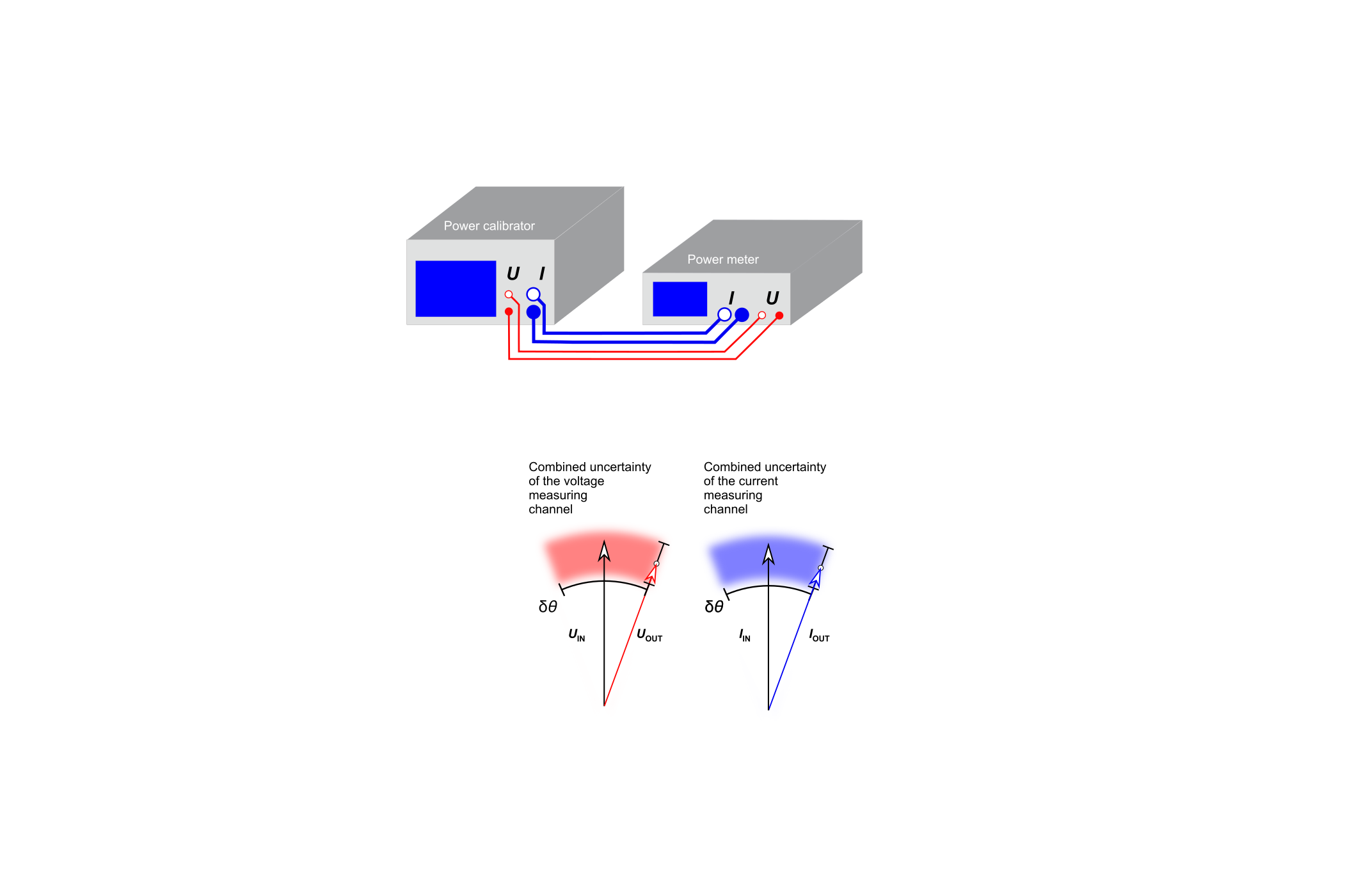
The power measuring instrument measures the output voltages and output currents of the instrument transformers. As per the definition, a power measuring instrument contains one voltage measuring channel and one current measuring channel. Similarly to the instrument transformers, for all calibrated voltage measuring ranges and current measuring ranges of the power measuring instrument the following measurement uncertainties are certified:
- Measurement uncertainty of the amplitude of the voltage measuring range
- Measurement uncertainty of the angle of the voltage measuring range
- Measurement uncertainty of the amplitude of the current measuring range
- Measurement uncertainty of the angle of the current measuring range
Normally the power measuring instrument needs to be sent to a further calibration laboratory for calibration.
The calibration of the power measuring instrument with evaluation of the calibration in the form of amplitude errors and angle errors for the current measuring channel and voltage measuring channel is shown schematically in the diagram.
Final measurement uncertainty of the power measuring system
Final measurement uncertainty of the power measuring system
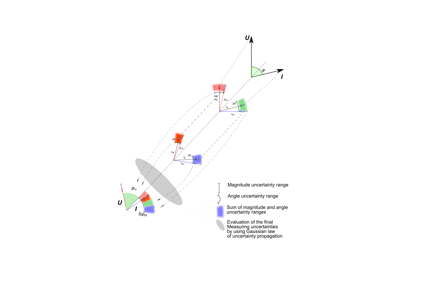
In order to assess the measurement results of a power measurement, the measurement uncertainty of the power measuring system needs to be determined on the basis of the measuring ranges used for the two instrument transformers and for the power measuring instrument. Here, the final measurement uncertainty of the power measuring system must be determined for every combination of the transformer measuring ranges and the measuring ranges of the power measuring system. The certified measurement uncertainties are combined together using the error propagation law. The operator of the power measuring system is responsible for determining the final measurement uncertainty of the power measuring system.
Conclusions
-
The need for two calibration laboratories increases the workload and expense for logistics and coordination of the laboratory work.
-
The responsibility for the final measurement uncertainty lies with the operator of the power measuring system.
-
The final measurement uncertainty of the power measuring system must be determined for every combination of the instrument transformer measuring ranges and the measuring ranges of the power measuring system.

